Medical electrical equipment, even though operating perfectly, may still be hazardous to the patient. This is because every piece of electrical equipment produces a leakage current. Learn how proper design ensures patient safety.
Electric equipment operating in the patient vicinity, even though operating perfectly, may still be hazardous to the patient. This is because every piece of electrical equipment produces a leakage current. The leakage consists of any current, including capacitively coupled current, not intended to be applied to a patient, but which may pass from exposed metal parts of an appliance to ground or to other accessible parts of an appliance.
Normally, this current is shunted around the patient via the ground conductor in the power cord. However, as this current increases, it can become a hazard to the patient.
Isolated systems are now commonly used to protect against electrical shock in many areas, among them:
- intensive care units (ICUs)
- coronary care units (CCUs)
- emergency departments
- special procedure rooms
- cardiovascular laboratories
- dialysis units
- various wet locations
Without proper use of grounding, leakage currents could reach values of 1,000 μA before the problem is perceived. A patient can be injured by a leakage current of as little as 10 to 180 μA. Ventricular fibrillation can also occur from exposure to this leakage current.
Leakage current is the current that flows from either AC or DC circuit in a piece of equipment to the chassis, or to the ground, and can be either from the input or the output. If the equipment is not properly grounded, the current flows through other paths such as the human body. This may also happen if the ground is inefficient or is interrupted intentionally or unintentionally.
Leakage currents are involuntary currents which flow when a resource or electrical medical device is operating in normal, faultless state. Therefore, leakage currents are not fault currents. Fault currents only occur in the event of a fault (e.g., defective insulation). Leakage current can flow from live parts through the intact insulation to protective earth or from a live part via the insulation to another live part.
Leakage currents are always present because there is no such insulation which insulates to 100% efficiency. Leakage currents are composed of ohmic and capacitive leakage currents. Ohmic leakage current is produced by the loss resistance of the insulation materials. Capacitive leakage current is inevitably produced where two electrically conductive surfaces or conductors are separated by insulation.
In practice, the ohmic shares can normally be ignored due to their minimal size. However, the capacitive leakage current plays an important part in the electrical safety test of resources and medical devices.
The amount of current that flows depends on:
- the voltage on the conductor
- the capacitive reactance between the conductor and earth
- the resistance between the conductor and earth
For medical electrical equipment, several different leakage currents are defined according to the paths that the currents take.
Leakage Current Classifications
Earth leakage current — Earth leakage current flows in the earth conductor of a protectively grounded piece of equipment. As long as the connection to earth remains closed, a person coming into contact with the metal enclosure of the equipment would be safe. But if the connection to earth opens, the impedance to earth through the person becomes much lower, thus creating a shock hazard.
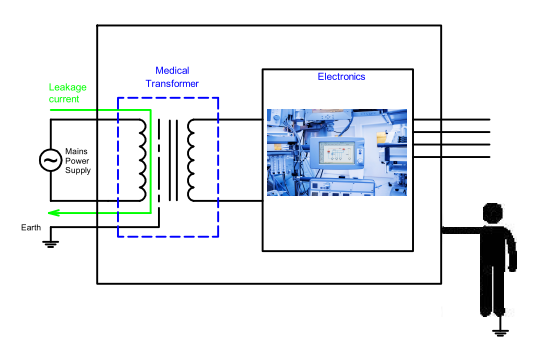
Because of this potential hazard, the impedance between the mains part of the transformer and the enclosure must be very high so that the potential for electric shock is minimized, even in the event of a fault in the earth circuit.
Enclosure leakage current — Enclosure leakage current flows from an exposed conductive part of the enclosure to earth through a conductor other than the normal ground conductor.
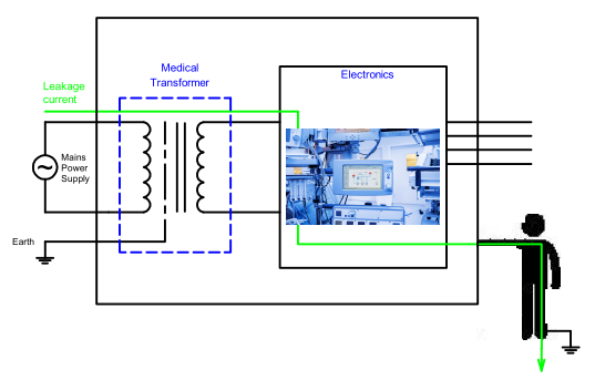
Great lengths are usually taken to protectively ground any conductive point in the enclosure. For this reason, testing is usually conducted on points of the enclosure that are not intended to be protectively grounded to cover the unlikely possibility that a fault may exist.
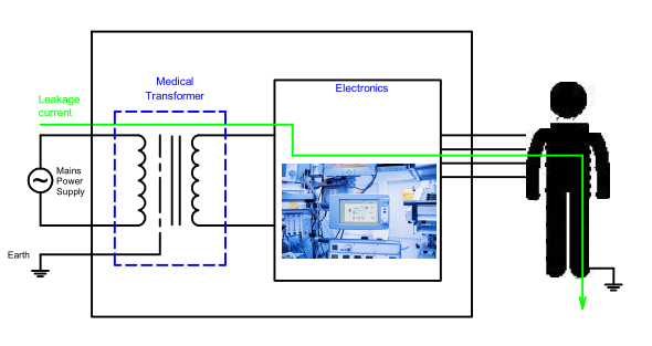
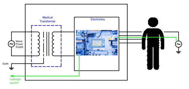
Patient leakage Current — Patient leakage current is the leakage current that flows through a patient connected to an applied part or parts. It can either flow from the applied parts via the patient to earth or from an external source of high potential via the patient and the applied parts to earth. The below figures illustrate the two scenarios.
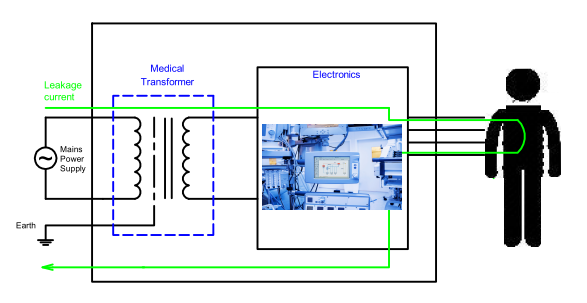
Patient auxiliary current — Patient auxiliary current is the current that normally flows between parts of the applied part through the patient, which is not intended produce a physiological effect.
Medical equipment that has direct physical contact with patients must limit its leakage current to the lowest prescribed levels. According to IEC 60601-1, the leakage current limits are provided in the table below.
| Leakage Current | Type B | Type BF | Type CF | |||
| NC | SFC | NC | SFC | NC | SFC | |
| Earth Leakage Current | 500 µA | 1 mA | 500 µA | 1 mA | 500 µA | 1 mA |
| Enclosure Leakage Current | 100 µA | 500 µA | 100 µA | 500 µA | 100 µA | 500 µA |
| Patient Leakage Current | 100 µA | 500 µA | 100 µA | 500 µA | 10 µA | 50 µA |
NC = Normal Conditions SFC : Single Fault Conditions
Leakage Current Standards
Today, the International Electrotechnical Commission (IEC) and Underwriters Laboratories (UL) are the two main regulatory bodies that determine and publish minimum safety standards for electronics products, including medical transformers.
UL is the official regulatory body for the United States, as it was appointed by the Occupational Safety and Health Administration (OSHA) to both test and certify all electronic equipment. The IEC is the standards body in Europe, working closely with each nation’s own national laboratory. UL 60601-1 is a standard that has been harmonized with IEC 60601-1.
The UL 60601-1 standard, which replaced the original UL 544 standard, specifies the maximum allowable leakage current values, which differ depending on equipment class and whether the equipment is located in a patient care area, such as an exam, overnight, or operating room. The largest allowable leakage current is 500 microamps (µA) for Class I non-patient care area equipment; as the equipment classes progress, this number steadily decreases. IEC 60601 follows very similar guidelines. Please note that these standards specify the performance of the completed medical device; they do not specify limitations of the transformer. However, having a low leakage transformer can greatly simplify the ease in which a completed device will meet leakage requirements.
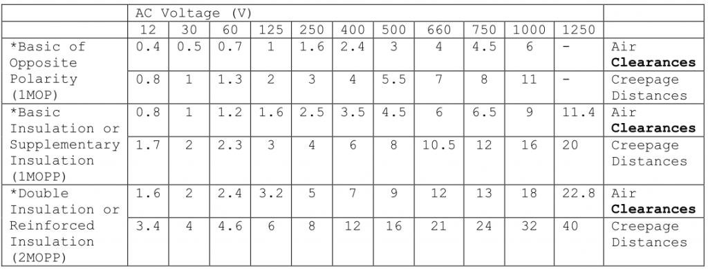
Creepage and Clearance Requirements
Creepage distance — the shortest distance along the surface of the insulating material between two conductive parts.
Clearance — Shortest path in air between two conductive parts.
Minimum spacings, as indicated below, shall be provided through air and over surface between uninsulated live primary parts of different potential, uninsulated live primary parts and dead-metal parts, uninsulated live secondary parts and dead-metal parts, and uninsulated live primary parts and uninsulated secondary parts. The spacings apply to coils, crossover leads, splices, uninsulated lead wires, and any turn of the primary winding to any turn of the secondary winding. The spacings do not apply to the turn-to-turn spacings of a coil.
Following on from this post, see our overview of Using Transformers for Electrical Isolation in Medical Devices
Learn more in our white paper — Improving Medical Isolation Transformers with Segmented Core Cap Technology
