A current transformer is an instrument transformer in which the secondary current, in normal conditions of use, is substantially proportional to the primary current and differs in phase from it by an angle which is approximately zero.
The design and testing of current transformers are governed by standard IEC 61869-2:2012 (replaces IEC 60044-1:1996)
The principle of operation of a current transformer is the same as that of the power transformer. The current transformer has a primary and a secondary winding. An alternating current flowing in the primary winding induces an alternating current in the secondary winding.
The primary winding may be a single turn or a small number of turns, the secondary winding will have many more turns depending on transformation ratio. The rated transformation is the ratio of the rated primary current to the rated secondary current.
Below is a simple circuit showing single turn 10 A primary winding and 1000 T CT with rated burden R 100 Ω.
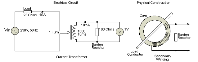
Ip = 10
Is = 10/1000 = 10 mA
Vb = 10 mA × 100 = 1 V
The secondary winding is terminated on the rated burden resistor, the value on which the accuracy requirements of the current transformer is based.
In an ideal current transformer, the current in the secondary winding will reflect the actual primary current without current ratio error or phase displacement. However, under normal conditions, there will be current ratio error and phase displacement between primary and secondary currents.
Current Ratio Error
Current Ratio Error expressed in percent is given by the formula:

Where:
Kn = Rated transformation ratio
Ip = Actual primary current
Is = Actual secondary current when Ip is flowing, under conditions of measurement
Phase Displacement
Phase Displacement is the difference in phase between the primary and secondary current vectors: θ=phase angle error being zero for ideal current transformer.
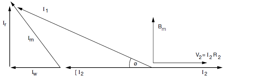
Where:
I1 = Primary current
I2 = Secondary current
N = Secondary turns
Im = Excitation current
Ir = Reactive component of Im
Iw = Watts loss component of Im
V = Secondary voltage
R2 = Burden Ω
θ = Phase angle error
e = Current ratio error
From the diagram, the primary current I1 differs from the secondary I2 in magnitude and phase angle.
The angle error θ is Sin-1 Ir/I1 and magnitude of I1 = √{ (I2N2 + Iw)2 + Ir2 }
In practice the angle is so small as to allow approximations:
θ = Ir/I1 radians and I1 = I2N2 + Iw
i.e. the current error is due to the watts loss component and phase angle is proportional to the reactive component Ir.
Ratio error can be corrected by amendment to the turns ratio, i.e. ± secondary turns.
Phase angle cannot be turns corrected since it is a function of the reactive component of the excitation characteristics of the core
Accuracy Class
Accuracy Class is a designation assigned to a current transformer where the errors remain within specified limits under prescribed conditions of use.
For example, if the accuracy class of a current transformer is 1, then the ratio error will be ±1% at the rated primary value.
In the case of metering CTs, accuracy class is typically 0.1, 0.2, 0.5, and 1
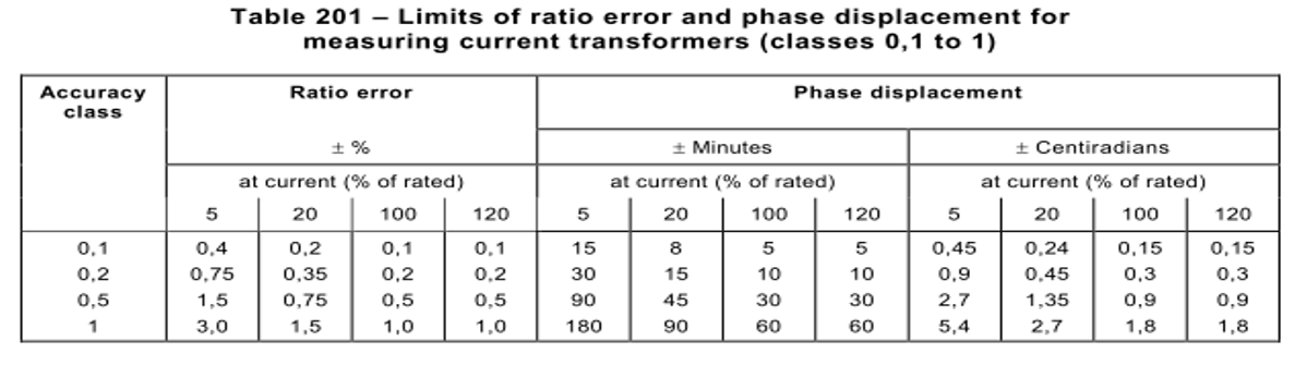
For classes 0.1, 0.2, 0.5, and 1, the current error and phase displacement shall not exceed the values given in table 201 when the secondary burden is any value from 25% to 100% of the rated burden.
Conclusion
Current transformers are suited to several applications, and many CT designs exist to suit them. We will discuss these different CT types in Part 2 of this series.