In our previous article, we covered the basic principles of current transformer (CT) design and operation. Now we will discuss a few of the common CT types and their applications.
Standard Measuring CT
Standard measuring current transformers are used in conjunction with ammeters to measure high currents which are stepped down to a standard output ratio of either 5 A or 1 A. The VA rating of the CT is matched with VA rating of the measuring instrument or ammeter.
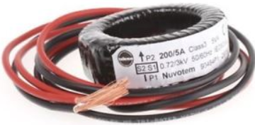
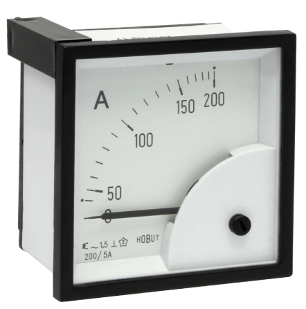
A 200/5 A FSD Series current transformer is used in conjunction with a moving iron ammeter with a scale from zero to 200 A. The ammeter is calibrated so that full-scale deflection (FSD) occurs when the output of the current transformer is 5 A.
The burden R of the ammeter should be low as possible to offer close to short a circuit to guarantee non-obstructed secondary current. Burden R used in conjunction with a voltmeter should also be as low as possible to keep CT secondary voltage low for increased accuracy.
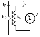
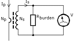
Typical VA ratings of standard measuring current transformers are 2.5, 5, and 10 VA. It is important for measuring current transformers to saturate at a level that ensures the safety of the measuring instrument at higher-than-rated current or under fault conditions.
If the ammeter is removed from the circuit the secondary winding effectively becomes open-circuited and the transformer acts as a step-up transformer. This due in part to the very large increase in magnetizing flux in the CT core because there is no opposing current in the secondary winding to prevent this.
This can result in a very high voltage being induced in the secondary winding equal to the ratio of Vp × (Ns/Np) being developed across the secondary winding.
For this reason, a current transformer should never be left open-circuited. If the ammeter (or load) is to be removed, a short-circuit should be placed across the secondary terminals first to eliminate the risk of shock.
Turns Ratio
The turns ratio of a current transformer can be altered by using multiple turns. The example below shows how a 300/5 A CT can be used as a 100/5 A CT by using three primary loops to reduce the turns ratio from 60:1 to 20:1. This enables a higher rated current transformer to be used to measure lower currents.
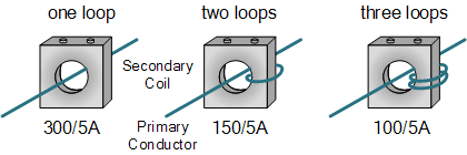
The limits for for ratio error for Class 3 & Class 5 measuring current transformers are shown below.

Ratio error is 3% and 5% respectively, with no requirement for ± phase displacement.
Applications for Class 3 & Class 5 measuring current transformers include:
- Overload Protection
- Current Monitoring Three Phase Generators
- Control Devices
- Control Panels
- Switchgear control and monitoring
- Distribution
While it is desirable to have zero phase shift between primary and secondary current, for 5 A measuring CT’s it is not so important since ammeters only show the magnitude of the current.
Metering CT
A metering current transformer is designed to measure current continuously and work accurately within the rated current range. Current error and phase displacement limits are determined by the accuracy class. Accuracy classes are: 0.1, 0.2, 0.5 and 1.
In wattmeters, energy meters, and power factor meters, phase shift produces errors. However, the introduction of electronic power and energy meters has allowed current phase error to be calibrated out.
When current exceeds the rating, the metering CT will saturate thereby limiting the current level within the instrument. Core materials for this type of CT typically have low saturation level, such as nanocrystalline.
Nuvotem AP Series and AQ Series are precision current transformers with typical accuracy of 0.1–0.2%, making them suitable for applications requiring high accuracy and minimum phase displacement.
Protection CT
A protection current transformer is designed to operate well into the overcurrent range. This enables the protective relays to measure fault currents accurately, even in very high current conditions. The secondary current is used to operate a protective relay which can isolate part of the power circuit experiencing a fault condition.
Core material for this type of CT has high saturation level and is normally made from silicon steel.
Knee Point Voltage
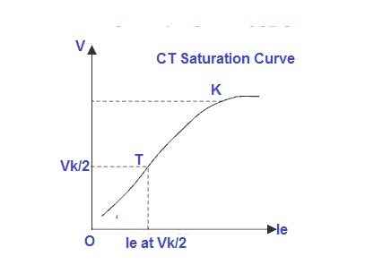
Beyond point K, we need to increase current to a larger extent to have some increase in voltage. This because the curve beyond point K becomes non-linear. The voltage at point K (Vk) is called the knee point voltage.
The knee point voltage of a current transformer is defined as the voltage at which a 10% increase in voltage of the CT secondary results in a 50% increase in secondary current. This also means that an increase in current of 50% will lead to an increase in voltage of just 10%.
The knee point voltage is important for protection class CTs, i.e. where the CT is used for protection purposes.
The burden of protection CTs is quite high when compared with a metering class CT, which means that voltage drop across the burden will be high. Therefore, the knee point voltage of a protection class CT must be more than the voltage drop across the burden to maintain the CT core in its linear zone.
Protection current transformers are usually defined in terms of composite error at an accuracy limit factor, i.e. how accurate the current transformer will remain when the primary current flowing is many times higher than normal under a fault situation.
Standard classes for protection CT’s are 5P 10 and 10P 10, where P is the designation for protection. The number before P indicates the composite error percentage. The number after the letter indicates the factor of primary current up to which composite error will be achieved, i.e. 10x the rated primary current in 5P 10 and 10P 10.
Protection devices will normally specify the classification for the protection CT intended to operate the protection device concerned.

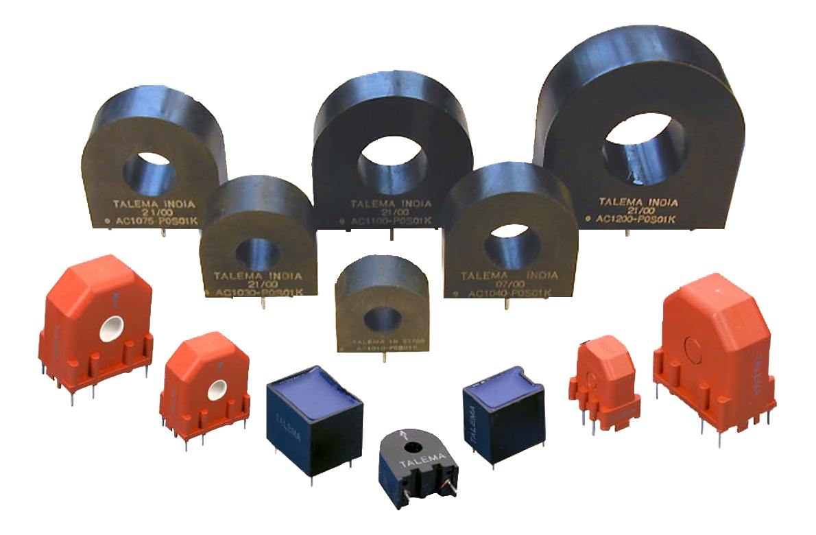
Talema manufactures an extensive range of standard and custom-designed 50/60 Hz toroidal current transformers. Each series is designed with specific characteristics in compact packages to suit most applications. Both PCB-mount and flying-lead options are available as well as the possibility for IDC or two-way connectors.

