Switched-mode power supplies (SMPS) are fairly complex compared to linear regulated power supplies. But this complexity results in a stable, regulated DC supply that can deliver power more efficiently for a given size, weight and cost. This article is the first in a series on switched-mode power supplies, their various topologies, benefits, and applications.
Introduction: Power Conversion Basics
A power supply takes unregulated power and converts it into stable, regulated power. Electronic equipment is generally powered by low voltage DC supplies, the source of which will be either a battery, a combination of battery and DC/DC converter or a power supply converting AC mains into one or more low voltage DC supplies.
A power supply unit is an important element in the process of power conversion. Almost all electronic equipment requires a DC supply that is well regulated, has low noise characteristics and provides a fast response to load changes. Some power supplies also provide isolation from the input to the output for safety and transient protection.
There are two types of regulated power supplies: linear regulated power supplies and switched-mode power supplies (SMPS). We will mainly discuss SMPS, but a quick comparison of the two types will provide some extra context.
Linear Power Supply vs. SMPS
The primary advantages of an SMPS are efficiency, size and weight. A linear power supply contains a mains transformer and a dissipative series regulator. This means the supply has extremely large and heavy 50/60 Hz transformers and very poor power conversion efficiencies, which are both serious drawbacks.
| Linear | SMPS | |
| Size | Large and heavy | Small and light |
| Efficiency | 30–40% | 70–95% |
| Complexity | Low | High |
| EMI | Low-noise | Filtering required |
| Output Voltage | Variable | Constant |
| Regulation Method | Dissipating excess power | Varying duty cycle of PWM |
| Cost | High | Low |
The design of switched-mode power supplies is fairly complex when compared to linear regulated power supplies. However, this complexity in design results in a stable and regulated DC supply that is capable of delivering more power in an efficient way for a given size, weight & cost.
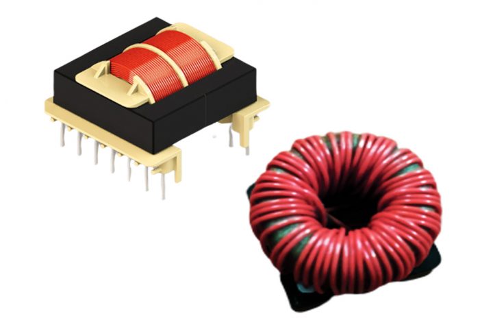
By utilizing high switching frequencies, the size of the magnetic components and associated filtering components in the SMPS are significantly reduced in comparison to the linear power supply. For example, an SMPS operating at 20 kHz produces a 4 times reduction in component size, and this increases to about 8 times at 100 kHz and above. This means an SMPS design can produce very compact and lightweight supplies. Nowadays, this is an essential requirement for the majority of electronic systems.
SMPS Overview
Switched-mode power supplies use high frequency switching devices to transfer electrical energy from source to load in a highly efficient way. The switching action is controlled by using pulse width modulation (PWM) and voltage regulation is achieved by varying the duty cycle of the PWM.
As electronic equipment becomes smaller and smaller, the market demands that power converters do the same. Since the introduction of switched-mode techniques, this has been an evolutionary rather than a revolutionary process. With the global market a reality, power supplies operate from wide input ranges to cover worldwide AC mains supply variations.
Basic SMPS Circuit
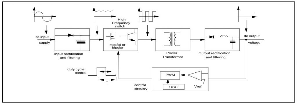
- Input rectifier and filter: Used to convert an AC input to DC. An SMPS with DC input does not require this stage. The rectifier produces unregulated DC which is then passed through the filter circuit.
- Inverter: The inverter stage converts DC (whether directly from the input or from the rectifier stage) to AC by running it through a power oscillator, whose output transformer is very small with few windings at a frequency 10 to few 100s of KHz.
- Switching transformer: If the output required is to be isolated from input, SMPS uses a high frequency transformer as an isolator between the switching element and output. This converts the voltage up or down to the required output level on its secondary winding.
- Output rectifier and filter: Converts AC output into DC.
- Regulation: Feedback circuit monitors the output voltage & current and compares it with the reference voltage & current to keep the output voltage regulated/constant.
SMPS Topologies
SMPS circuits contain networks of transformers, energy storage and filter inductors, capacitors, and power handling electronic switches and rectifiers. Their particular arrangement is referred to as a topology.
An SMPS reduces size and improves efficiency by increasing the frequency of operation. The compromises are increased ripple and noise (both conducted and radiated EMI) on the output, which have to be managed
Factors to be considered while selecting a topology for a particular application:
- Is input-to-output dielectric isolation required?
- Is the output voltage higher or lower than the whole range of the input voltage?
- Are multiple outputs required?
- Does the prospective topology place a reasonable voltage stress across the voltage semiconductors?
- Does the prospective topology place a reasonable current stress across the voltage semiconductors?
- What is the maximum voltage applied across the transformer primary and what is the maximum duty cycle?
- What is the maximum power rating?
SMPS Types
SMPS can be classified into two types based on circuit topology: non-isolated converters and isolated converters.
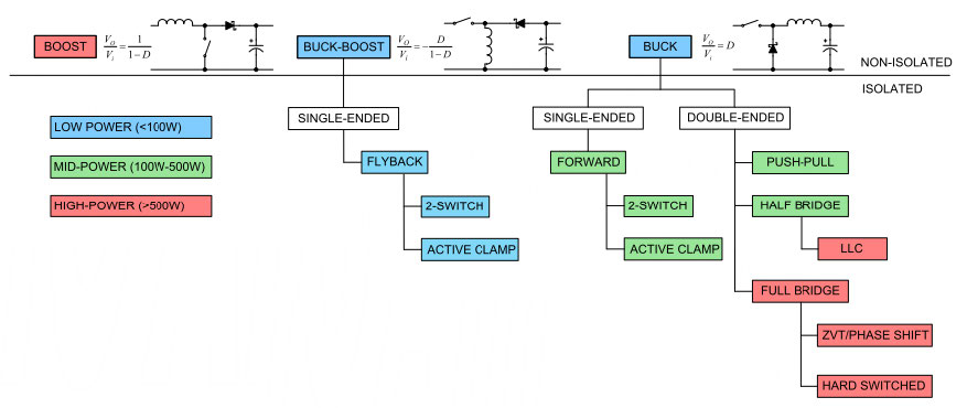
- Non-isolated converters: the input source and the output load share a common current path during operation and energy is transferred through energy storage elements (Inductors & Capacitors).
- Isolated converters: the energy is transferred via mutually coupled magnetic components (Transformers), wherein the coupling between the supply and the load is achieved solely via an electromagnetic field, thereby permitting galvanic isolation between input and output.
In most applications, the SMPS topology contains a power transformer to provide isolation, voltage scaling through the turns ratio, and the ability to provide multiple outputs. However, there are non-isolated topologies such as the buck, boost and buck-boost converters, where the power processing is achieved by inductive energy transfer alone.
The table below outlines the typical maximum output power levels of different topologies.
| Topology | Power Range (W) |
| Buck | 0–1000 |
| Boost | 0–150 |
| Buck-Boost | 0–150 |
| Flyback | 0–150 |
| Forward | 0–250 |
| Push-Pull & Half-Bridge | 500 |
| Full-Bridge & LLC Resonant Half-Bridge | 1000 |
| ZVT Full-Bridge | >1000 |
| Multiple ZVT Full-Bridge in Parallel | >2000 |
Switching methods
The switching operation can be ’hard’ or ’soft’.
| Hard Switching | Soft Switching | |
| Frequency | Fixed | Variable |
| Number of Components Req’d | Less | More |
| EMI | Severe | Low |
| Switching Losses | High | Low |
| Applications | Low power / low performance requirements | High power / high performance requirements |
| Cost | Low | High |
| Control | Simple | Complex |
| Modulation Scheme | Versatile | Limited |
Conclusion
Despite being comparatively complex, switched-mode power supplies have become increasingly popular due to their size, weight, and efficiency benefits.
In our next article, we will take a closer look at non-isolated converters and their applications.