The previous article in our series on switched-mode power supplies (SMPS) covered non-isolated converter topologies. Now we will investigate isolated converters, starting with asymmetrical converter topologies.
Isolated Converter Overview
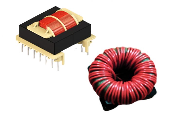
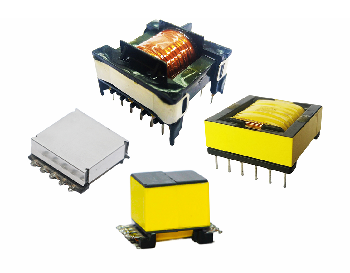
Isolated topologies in switched-mode power supplies use a high frequency transformer as an isolator between the switching element and output. Depending on the transformer turns ratio, the output voltage can be higher or lower than the input. Transformer-based SMPS topologies can be designed to generate multiple output voltages by using multiple windings.
Isolated converters are split into two main categories, called asymmetrical and symmetrical converters, depending upon how the transformer is utilized.
In asymmetrical converters the magnetic operating point of the transformer is always in one quadrant. The core has to be reset each switching cycle to avoid saturation, meaning that only half of the usable flux is ever exploited. Flyback and forward converters are both asymmetrical converters.
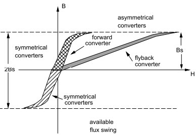
The B-H curve clearly indicates that the flyback converter is operated at a lower permeability (B/H) and lower inductance than the other topologies. Since the flyback transformer is actually a coupled inductor that stores all of the energy before sending it into the load, an air gap is required to store this energy and prevent core saturation. The air gap has the effect of reducing the overall permeability of the core. All of the other converters have true transformer action and ideally store no energy, thus no air gap is needed.
Symmetrical converters require an even number of switches and the full available flux swing in both quadrants of the B-H loop is used, thus utilizing the core much more effectively. Therefore it can produce more power than asymmetrical converters. Push-pull, half-bridge, and full-bridge converters are all symmetrical converters.
Asymmetrical Converters
Flyback Converter
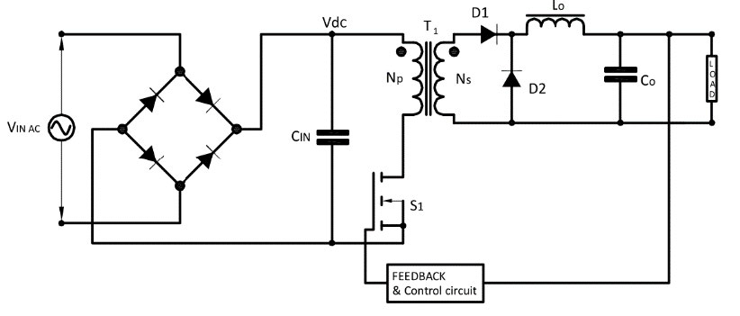
A flyback converter (FBT) is also called an isolated buck-boost converter and it is used for both AC-DC & DC-DC conversion with galvanic isolation between the input and output. Flyback converters provide isolation through the use of a transformer that acts as the storage inductor. The transformer not only provides isolation, but by varying the turns ratio, the output voltage can be adjusted and multiple outputs are possible.
Flyback converters are widely used for low power applications up to 150 W and can also be designed for higher output voltages up to 400 V at a low output power (15-20 W).
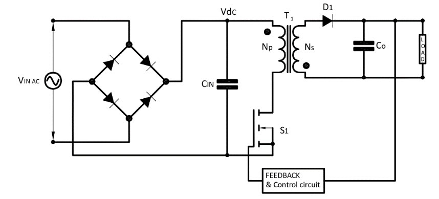
The main components of a flyback converter are the top switch, oscillator circuit, transformer, diode and capacitor. The flyback transformer works differently from a normal transformer, since the primary & secondary do not conduct simultaneously.
The principle behind the flyback converter is based on storage of energy in the inductor during Ton period and the discharge of the energy to the load during Toff period.
When the switch is turned ON, the primary winding of the transformer is directly connected to the input and its dot becomes positive with respect to non-dot end. The voltage induced in the secondary winding is negative, the diode is reverse-biased (blocked) so the transformer behaves as an inductor. The primary current and magnetic flux in the transformer increases storing energy. During the Ton period, the output capacitor supplies energy to the load. So the output capacitor value should be large enough to supply the load current for the time period Ton, with the maximum specified droop in the output voltage.
When the switch is turned OFF, the secondary voltage reverses due to the collapsing magnetic field, the output rectifier diode D1 becomes forward biased, and energy stored in the transformer core recharges the capacitor and supplies the load.
At the end of the ON period, when the switch is turned OFF, there is no current path to dissipate the stored leakage energy in the magnetic core of the flyback transformer. There are many ways to dissipate this leakage energy, including the single switch with snubber design and the two-switch topology.
Single-switch implementation is efficient however it requires snubber design or resonant approach to clamp voltage spikes generated by the leakage inductance of transformer. Two-switch topology actively clamps the voltage spikes but increases circuit complexity.
Magnetizing stored energy in Flyback Transformer:

Where EP = Joule IPK= Amps & LM= Henries
Vout/Vin Relationship

Vin > Vout or Vin < Vout
Range of duty cycle = 0 to < 0.5
Air Gap
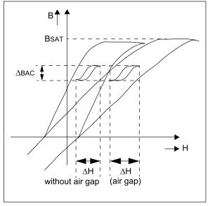
In order to obtain sufficiently high stored energy, the primary inductance has to be significantly lower than required for a true transformer and high peak current is needed. This is normally achieved by “gapping” the core. The gap reduces the inductance, and most of the high peak energy is then stored in the core gap, thus preventing core saturation. The air gap doesn’t change the saturation flux density (BSAT) value of the core material; however, it increases the magnetic field intensity, H, to reach saturation and reduces the residual flux density BR.
Operating Modes
The flyback converter has two operating modes depending whether the primary inductance of the transformer is completely demagnetized or not.
In discontinuous mode, the secondary current falls to zero in each switching period, and all of the energy is completely delivered to the load before the next cycle, and there is also dead time between the instant the secondary current reaches zero and the start of next cycle. This is called triangular operation.
In continuous mode, the energy stored in the inductor is not completely transferred to the output capacitor and load before the next charging period occurs. This is called trapezoidal operation. The main advantage of continuous mode is that the peak currents flowing are only half that of the discontinuous for the same output power, hence, lower output ripple is possible. However, the core size is about 2 to 4 times larger in continuous mode to achieve the increased inductance needed to reduce the peak currents and achieve continuity.
Advantages
- A flyback transformer is in reality a storage inductor, therefore no separate inductor is needed. Simple circuit and lowest component count, makes the flyback topology a cost-effective and popular topology
- Easily accommodates multiple outputs
Disadvantages
- Large output capacitor required to reduce ripple current
- High isolation requirement may reduce close coupling of primary and secondary winding
- High eddy current loss in the air gap area
- EMI Considerations
- Poor transformer utilization as it is single ended
Applications
- Low-power switch-mode power supplies (cell phone charger, standby power supply in PCs)
- Low-cost multiple-output power supplies (e.g., main PC supplies <200 W)
- High voltage supply for the CRT in TVs and Monitors
- High voltage generation (e.g., for xenon flash lamps, lasers, copiers, etc.)
- Isolated gate driver
Forward Converter
A forward converter is essentially a buck converter that uses a unidirectional pulse transformer to provide galvanic isolation for the load and to provide voltage conversion (AC-DC & DC-DC) step-down function.
The forward converter, when compared with the flyback circuit, is generally more energy efficient and is used for applications requiring little higher power output (in the range of 100 W to 250 W). However, the circuit topology, especially the output filtering circuit is not as simple as in the flyback converter.
In contrast to the flyback, the forward converter has a true transformer action (which is based on a transformer with same-polarity windings, higher magnetizing inductance, and no air gap), and does not store energy during the conduction time of the switching element. This is because ungapped core transformers cannot store a significant amount of energy like inductors can. Instead, energy is passed directly to the output of the forward converter by transformer action during the switch conduction phase. The output voltage is determined by the input voltage, the transformer turns ratio and the duty cycle. Energy is stored in the output stage of the converter in the inductor and capacitor. The output inductor reduces the ripple currents in the output capacitor and the volume of the transformer is dependent on switching frequency and power dissipation.
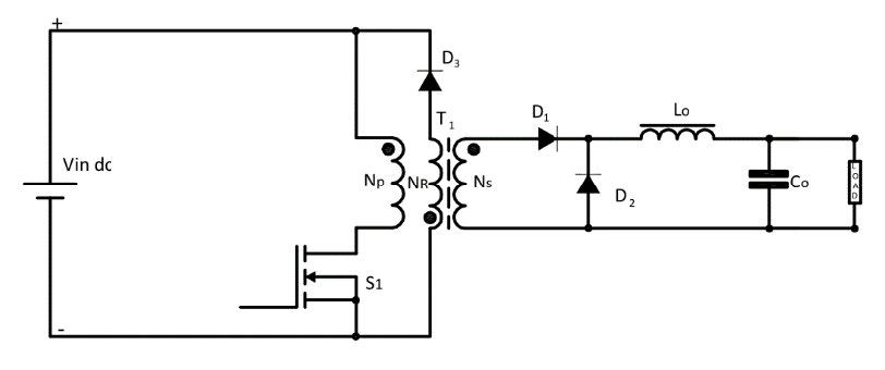
When the switch is ON, the energy is transferred to the load and stored in Lo through D1 and transformer.
When the switch is OFF, the energy stored in Lo is transferred to the load through D2. Diode D1 remains off during this mode and isolates the output section of the circuit from the transformer and the input.
Vout/Vin Relationship

Range of duty cycle = 0 to < 0.5
At the end of the ON period, when the switch is turned OFF, there is no current path to dissipate the stored energy in the magnetic core. Whenever a core is driven in a unidirectional fashion (current only being driven from one direction into the primary) the core must be reset. The core of the transformer has been magnetized by the magnetization current. The remanence of the core material would cause the core to saturate within a few switching cycles, so it must be demagnetized after each switching period. Various techniques have been used for this purpose, including:
- One switch with reset winding
- Two switch forward
- Active clamp forward
One switch with Reset Winding
The simplest option is one switch with Reset winding. In this method, the flux stored inside the magnetic core induces a negative voltage at the dot end of the NR winding, which forward biases the diode D3 and resets the magnetizing energy stored in the core. Thus the NR winding is called the reset winding. Resetting the magnetizing current during the OFF period is important to avoid saturation.
The reset winding is wound bifilar with the primary to ensure good coupling and minimize leakage inductance, and is normally made to have the same number of turns as the primary. (The reset winding wire gauge can be very small, since it only has to conduct the small magnetization current.) The time for the magnetization energy to fall to zero is thus the same duration as the switch on-time. This means that the maximum theoretical duty ratio of the forward converter is 0.5 and after taking into account switching delays, this falls to 0.45. Maximum blocking voltage seen by the switch will be more than twice the input voltage due to the nonlinearity of components and the leakage inductance of the transformer.
The incomplete utilization of the magnetics, the maximum duty cycle limit, and the high voltage stress of the switch make a forward converter feasible for the output power up to 150 W. Its non-pulsating output inductor current makes the forward converter well suited for the application involving a very high load current (> 15 A). The presence of the output inductor limits the use of a forward converter in a high output voltage (> 30 V) application, which requires a bulky inductor to oppose the high output voltage.
Two switch forward
In order to avoid the use of higher voltage switches, the two-switch forward method of demagnetizing the core can be used. The voltage across the switch is again clamped to Vin, allowing the use of faster and more efficient 400 V or 500 V devices for 220 V mains applications. The magnetization reset is achieved through the two clamp diodes, permitting the removal of the reset winding.
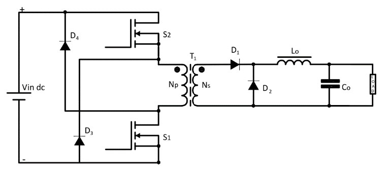
The two-switch version is popular for off-line applications. It provides higher output power level (150 W to 350 W) and faster switching frequencies. The disadvantages are again the extra cost of the higher component count, and the need for an isolated drive for the high line switch.
Active clamp forward
Further possibilities for demagnetization by using forward converter with active clamping. For the active-clamp forward, the capacitor on the transformer generates a higher negative voltage, so that the demagnetization is achieved in a shorter time. This means that duty cycles higher than 50% are possible.
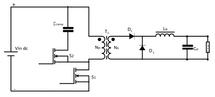
The addition of the active clamp has a number of advantages. The transformer reset winding is no longer required and the voltage across switch S1 peaks at Vin and not 2 × Vin. The overall efficiency is higher because the diode losses are avoided and only the demagnetizing current flows through switch S2.
The disadvantage of the active clamp is that a second PWM signal needs to be generated and switch S2 needs a high-side driver. However, there are many controller ICs that integrate the necessary timing circuits and high-side drivers internally. The clamp capacitor Cclamp has a high ripple current, so great care must be taken to ensure that it does not overheat.
Advantages
- High power range compared to flyback
- Better transformer utilization
- Lower peak current
- Low ripple current (small output capacitor)
- Multiple outputs are possible
- Relatively simple circuit with medium component count
Disadvantages
- Cost is increased because of the extra output inductor and freewheeling diode.
- Higher component count, particularly with multiple regulated outputs.
- High voltage requirement for top switch
- Large output inductor required
Applications
- ATX Power supply
- AC Adapters
- Solar power system
- Personal computer
The next article in our SMPS series will cover the second main group of isolated topologies: symmetrical isolated converters.