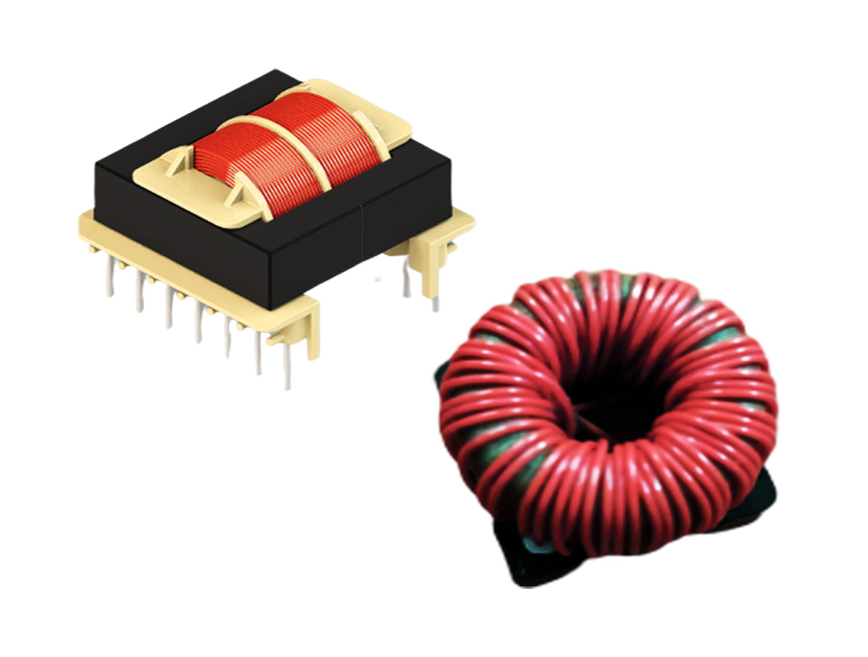
Several important factors need to be considered when designing an optimized gate drive transformer (GDT). This article discusses several GDT design considerations, as well as ideal applications for their use.
Two of the critical components to control when designing a gate-drive transformer are the leakage inductance and distributed capacitance. High leakage inductance and distributed capacitance may cause an undesirable output signal such as phase shift, timing error, noise, or overshoot.
1. Leakage Inductance
Gate drive transformers handle very low average power, but deliver high peak currents at turn-on and turn-off. To avoid time delays in the gate drive path, low leakage inductance is a must. GDTs must have good coupling between primary and secondary. Poor coupling will lead to isolated power switches to switch slower than the grounded/low side power switches and also may destroy the power switches.
2. Distributed Capacitance
The distributed capacitance of gate drive transformers should be kept low to avoid large common mode currents which would flow at the device common (source/emitter) terminal. Higher capacitance results when a winding has many turns, low insulation thickness, and the turns are not laying uniformly during the winding process.
3. Core Material
Selecting an appropriate core is important to achieve optimal performance from a GDT/pulse transformer. In general, the best materials are those that offer high permeability, large values for BSAT and low losses from switching frequency up to ten times. High permeability ensures desired magnetizing inductance using the fewest turns. Fewer turns with single-layer winding help guarantee low leakage inductance, distributed capacitance, and winding resistance.
4. Air Gap
No air gap is required. An air gap in the magnetic path decreases the permeability of the core material. This creates the need for a greater number of turns, resulting in poor coupling which leads to flux leak outside of the core. Also, ensure that there is no DC current in the windings that could cause saturation.
5. Core Size
Generally, choose a toroidal core with a diameter large enough to fit the required number of turns in a single layer. Usually bigger cores are used for lower frequencies to achieve sufficient magnetizing inductance with fewer turns. Also, the inside diameter of the toroid should not be excessive (which leads to higher leakage inductance).
6. Winding Placement
Do not separate primary and secondary winding around the toroidal core or wind all the turns around a small section of the toroid circumference (creating sectors). Spacing between the primary and secondary coil gives relatively poor magnetic coupling and increases leakage inductance. Hence interleaved winding techniques should be employed (e.g., bifilar/trifilar) and windings should be evenly distributed around the core.
Rather than leaving extra space between turns, use the thickest wire insulation that will allow for reduced winding space as much as possible between turns around the toroid ring.
If a non-toroidal core shape is used (e.g., E-I/E-E/ETD), the primary and secondary windings should be concentric and on the center leg of the core. Also, the primary should be closest to the center and the secondary should be wound over the top of the primary.
Where top and bottom switching devices in a bridge are being driven from one GDT, the secondary winding which is used to drive the bottom switching device should be next to the primary. The secondary winding which is used to drive the top switching device should be outermost from the core. In such a case, the secondary winding connected to the bottom switching device acts as an electrostatic shield between the high dv/dt present on the top switch and the primary. Fast transients are capacitively coupled safely to the ground through the bottom device, rather than being coupled back to sensitive drive circuitry.
7. Avoiding Core Saturation
The average voltage across the transformer winding must be zero over a period of time. Even a small DC component can cause “flux walk” and eventual core saturation. In order to avoid saturation, the magnetizing inductance (primary inductance) of the transformer must be high to keep the magnetizing current low. However, leakage inductance normally increases with increasing magnetizing inductance, so do not make the primary inductance too high.
Core saturation limits the applied volt-time product (V*T) across the windings. The transformer design must anticipate the maximum volt-time product under all operating conditions, which must include worst-case transients with maximum duty ratio and maximum input voltage at the same time. An appropriate margin between worst-case peak flux density and saturation flux density must be provided (~1:3).
If operation in any one quadrant of the B-H loop is chosen, care should be taken for resetting the core. A significant portion of the switching period might be reserved to reset the core of the main power transformer in single-ended applications (working only in the first quadrant of the B-H plane) such as the forward converter. The reset time interval limits the operating duty ratio of the transformer. This is rarely an issue even in single-ended gate drive transformer designs because they operate with bi-directional magnetization.
8. Dielectric Isolation
The dielectric isolation of the transformer should be able to withstand at least twice the input voltage. For a ground-referenced floating drive, keep 500 V isolation if a 400 V pre-regulated PFC exists.
Triple insulated wire must be used for more than 3 KV isolation requirements.
General Gate Drive Transformer Attributes
Advantages
- There is no propagation delay in a transformer to carry signals from the primary side to the secondary side.
- Several thousand volts of isolation can be built in between windings by proper design.
- There is no need for a separate isolated power supply.
- Using modern high permeability cores, tiny GDTs are now available that meet the most stringent design specifications.
- Depending on the drive current and voltage required, it gives step-up / step-down facility.
- GDTs are highly efficient.
- GDTs provide galvanic isolation (between the control circuit and power electronic circuits) and impedance matching.
Disadvantages
- Gate drive transformers are not suitable for DC and can be used only for AC signals (time-varying signals).
- Large duty ratios (more than 50%) cannot be handled by the transformer without being saturated (due to the transformers operating only at AC signals — the core flux must be reset each half cycle in order to maintain a volt-second balance) unless AC coupling capacitors and Zener diodes are employed. However, this increases the design board size and parasitic components which in turn increases power losses in the driver circuit.
- The transformer saturates at low frequencies hence it can be used only for high frequencies.
- Due to magnetic coupling, signal distortion, duty cycle limitation, and larger size, GDTs are undesirable for high power, high-density synchronous rectification applications.
- It is difficult to implement overload/short circuit protection for the upper power device.
- GDTs are not suitable for normally ON devices.
- The transformer primary has to be driven by high-speed buffer for high power which is complex and costly for good bandwidth.
- Transformers designed for low coupling capacitance have high leakage inductance which limits PWM slew rate.
- A large transformer has high coupling capacitance, which causes high circulating currents from dv/dt across the transformer.
- The transformer requires special construction to meet safety standards for isolation.
- The transformer must reset between pulses, thus pulse width limits and reset voltage limits must be considered.
Applications
- Solar inverters
- Converter for wind turbine
- Servo drives with high switching frequencies for high-speed control
- Switched-mode power supplies (SMPS)
- Welding equipment
- Uninterruptible power supplies (UPS)
- Motor control systems
- Electric vehicles and hybrid electric vehicles
- Industrial battery chargers
- Medical devices
Conclusion
Now that you have considered these different factors, you are ready to start designing. The final article in our GDT series outlines a 12-step process for designing gate drive transformers


