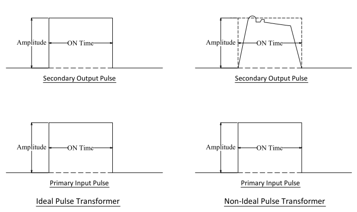
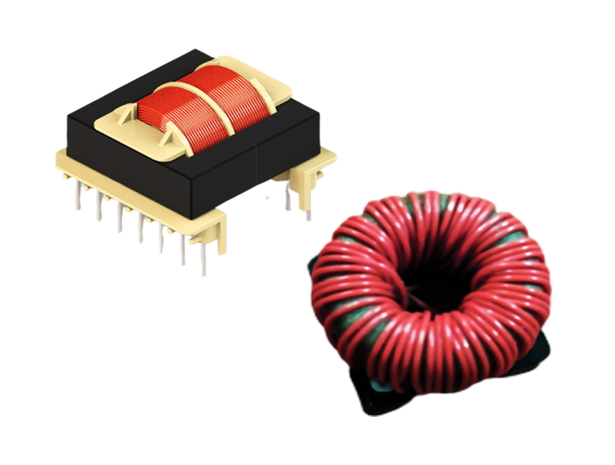
A gate drive transformer must reproduce the shape of an input pulse as accurately as possible at its secondary terminals.
The performance of a gate drive transformer’s pulse characteristics is specified in terms of its effect on the shape of the pulse input current/voltage. It is important that the transformer must reproduce the shape of the input pulse as accurately as possible at its secondary terminals, and there should be minimum shape distortion while transferring pulse from the primary to secondary.
Ideally, a pulse waveform should be perfectly rectangular, and all signal transitions should take place in zero time. But in the real world, ideal input pulse cannot be obtained due to parasitic elements, output response distortion, and the inability of current to change instantaneously.

The input voltage to the gate drive transformer is of a discontinuous nature. The pulse width varies from a fraction of a microsecond to about 25 microseconds.
Parasitic elements cause overshoot, delay and ringing, and non-ideal components (transients) cause the flat portions of the pulse to deviate from a perfect level. Therefore, transformers are designed in such a way that the critical parasitic leakage inductance and distributed capacitance are extremely low which improves the overall performance of the gate drive circuit.
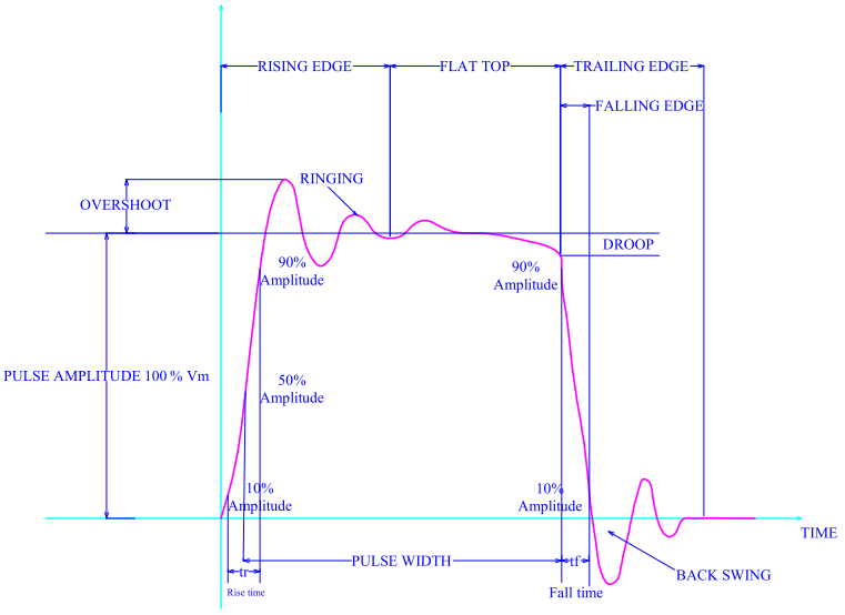
Basically, a typical pulse wave has four regions:
- Rising edge
- Flat top of the pulse
- Falling edge
- Trailing edge
The rising edge occurs in response to the transition of the input signal from the low to high level.
The flat top of pulse region occurs later, when rising edge transients are no longer present and the amplitude of the pulse is approximately a constant value.
The falling edge is the transition going from a high level to a low level.
The trailing edge occurs after the falling edge transients have settled out and the signal is at a constant low level.

Pulse response also includes various parameters which define the limits of allowable pulse distortion:
Pulse Amplitude – The maximum absolute peak value of the pulse excluding unwanted spikes.
Rise Time (Tr) – The time taken by the output pulse to raise from 10% of peak pulse amplitude to 90% of peak pulse amplitude during its first attempt.
Overshoot – The amount by which the output pulse exceeds the peak amplitude. Overshoot occurs on the initial rise of the signal pulse.
Pulse Width/Pulse Duration – The time interval between first and last instants at which the instantaneous amplitude reaches 50% of the peak amplitude (or) Duration of time between the leading and trailing edges of a pulse.
Droop – The displacement of the pulse amplitude during its flat response or the slow decay or reduction in voltage of the level of a voltage pulse. This is also called voltage droop.
Fall Time –The time taken by the output pulse to decrease from 90% of peak pulse amplitude to 10% of peak pulse amplitude during trailing edge response.
Back Swing – The portion of trailing edge which extends below the zero amplitude. This is also called as under-shoot which occurs on the final fall of the signal pulse.
Pulse Spike – A short duration large change in pulse amplitude, greater than either ripple or over-shoot voltage and lasting less than 10% of the pulse width
Pulse Average Time – The time duration from a point on the leading edge which is 50% of the maximum amplitude to a point on the trailing edge which is 50% of the maximum amplitude
Pulse Delay Time – The time interval from a point at which the leading edge of the input pulse has risen to 10% of its maximum amplitude to a point at which the leading edge of the output pulse has risen to 10% of its maximum amplitude.
Pulse Ringing – A damped oscillation that occurs at each edge of a pulse. Pulse ringing causes a positive overshoot [the maximum positive voltage] and a positive undershoot; in addition to a negative overshoot [the maximum negative voltage] and a negative undershoot. Pulse ringing differs from pulse ripple in that the signal is damped and not a constant amplitude.
Pulse Ripple – The application of varying AC voltage (sine wave) to a pulse.
Pulse Rate – The time interval between the start of one pulse and the beginning of the next pulse, measured at the same voltage level for both pulses. It also called as Pulse-Repetition Rate
Pulse Oscillations – An oscillation riding on a pulse may appear the same as pulse ripple.
Pulse Storage Time – The time interval from a point 10% down from the maximum amplitude on the trailing edge of the input pulse to a point 10% down from the maximum amplitude on the trailing edge of the output pulse.
Pulse Time – The time interval from the point on the leading edge which is 90% of the maximum amplitude, to the point on the trailing edge which is 90% of the maximum amplitude.


