Following these 12 steps when designing gate drive transformers will ensure a long component life and optimal performance.
The following parameters are essential for designing GDTs:
- Input voltage range
- Power level
- Ratio de rotation
- Operating frequency
- Cycle d'utilisation
- Dielectric strength
- Safety requirements
- Ambient temperature
- Size requirements
Step 1: Core Choice & Shape
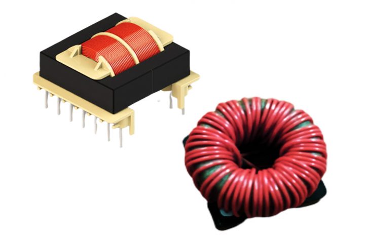
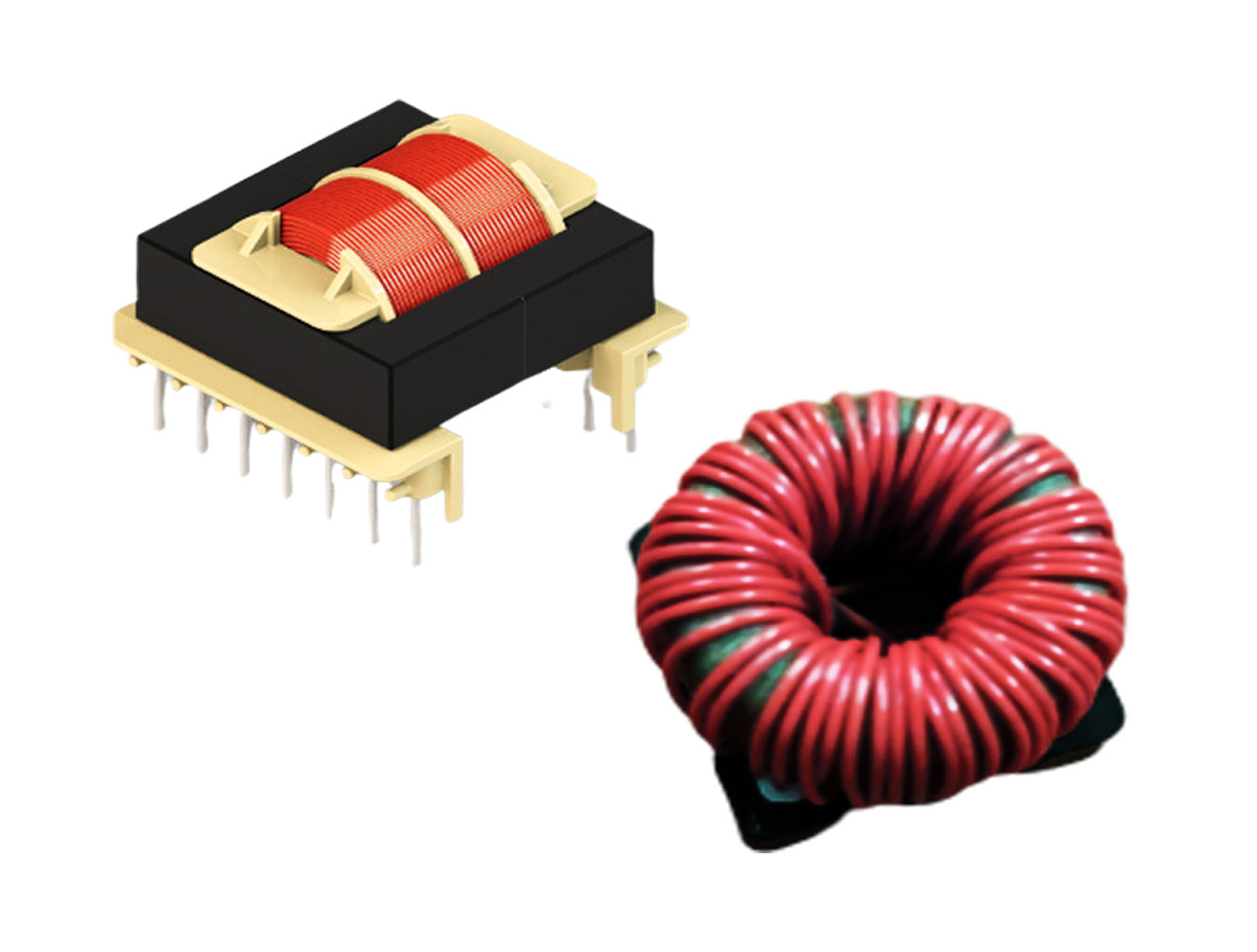
The first task is to choose core size. The designer can make their preliminary core choice based upon the power requirements of the application and the frequency. Selecting an appropriate core is important to achieving optimal performance from the transformer. Ferrite or tape wound cores (with high permeability and high Bsat) are the best choice for high-frequency applications that operate in KHz ranges. The most popular shapes are toroids, pot, and RM cores, however many other shapes also work. Ungapped cores are usually preferred since inserting air gaps corresponds to decreasing the equivalent permeability of material and increase the leakage inductance.
Core size
There are many variables involved in estimating the appropriate core size.
- One way to select the proper core is to refer to the manufacture’s core selection guide.
- The core area product (WaAc), obtained by multiplying the core cross-section area by window area available for winding is widely used for an initial estimate of core size for a given application.

Kf = Form factor; for square wave Kf = 4
Ku = Window utilization factor
J = Current density
Bmax = Operating flux density
F = Switching frequency
Po = Output power
Step 2: Volt-Time Product (V-µSec) value
Determine the V-T value based upon the maximum allowable duty cycle and the frequency.


T = Switching period
F = Operating frequency
VPEAK = Peak drive voltage
D =Duty Cycle
Step 3: Set BPEAK & ΔB value
An appropriate margin between worst-case peak flux density and saturation flux density must be provided; usually a 1:3 margin is desirable.
Example: Saturation flux density of ferrite material
Bsat = 0.30T @ 100°C, BPEAK selected = 0.10T & = 0.20T
BPEAK = Peak flux density in steady state operation
ΔB = Peak-Peak flux density in steady state operation
Step 4: Primary Turns
Determine the minimum number of primary turns required to support the worst case (V-T) volt-time product.

V.T = volt-time product in V-sec
ΔB = Peak to Peak flux density in Tesla
Step 5: Secondary Turns
Choose the secondary turns based on Turns ratio.
Turns ratio usually 1:1/1:1.5/1:2 and < 30 turns per winding is better to improve coupling. In order to minimize leakage inductance and AC winding resistance, each winding should occupy a single layer only.
Step 6: Primary Inductance
Calculate the required magnetizing inductance.

Step 7: Magnetizing current & RMS current
Calculate the required magnetizing current


Step 8: Wire size
Once all the winding turns are determined, the wire size should be properly chosen to minimize the winding conduction loss and leakage inductance. The winding loss depends on the RMS current value, the length and the cross-section of the wire, and also the transformer structure. Assume current density is typically 3 ~ 6 A/mm2.
Step 9: Core loss
The operating flux density level needs to be determined to estimate the core loss. With the frequency and B level known, core loss can be estimated from the material core loss curves.

Pv = Watts / mm3
Ve = Effective volume of core mm3
Step 11: Copper loss
In a transformer, copper loss is a function of AC & DC Resistances.

Step 12: Temperature rise
Temperature rise is important for overall circuit reliability, Estimate temperature rise.
Total loss in watts & surface area in cm2