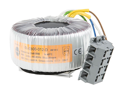
Following these 12 steps when designing toroidal transformers will ensure a long component life and optimal performance.
Step 1: Calculate the Transformer’s EMF
According to Faraday’s equation for induced voltage in a transformer winding:

Where E is voltage in volts
N is the number of turns
Ac is the cross-sectional area of the magnetic core in mm²
B is flux density in tesla
Note: Toroidal transformers usually operate at higher flux density than conventional laminated transformers.
Step 2: Calculate the Power Rating

Where VA is volt-ampere
VFL is full-load AC secondary voltage in volts
IFL is full-load AC secondary current in amperes
Step 3: Duty Cycle
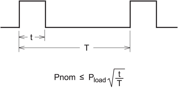
A smaller transformer can be used if the load is intermittent. Because the output power in this case significantly exceeds the nominal power, the secondary voltage drops below the voltages given. The voltage drop increases proportionately with the current being drawn.
Step 4: Line Frequency
The majority of toroidal power transformers are designed to operate in 50/60 Hz, 60 Hz, or 400 Hz applications. As the frequency increases, the transformer size decreases accordingly. A 60 Hz toroidal transformer will be ~20% smaller than a 50 Hz toroidal transformer.
Step 5: Turns Ratio

Where Vp is primary voltage in volts
Vs is secondary voltage in volts
Np is the number of turns in the primary
Ns is the number of turns in the secondary
Step 6: Regulation

Where VNL is no load AC secondary voltage in volts
VFL is full load AC voltage is volts
Step 7: Voltage Drop
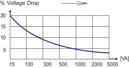
The secondary voltages and currents are valid for normal output power. At partial load, the output voltage, as a function of transformer size, will be accordingly higher. The below figure shows the voltage increase for Talema standard toroidal transformers for partial loads.
Step 8: Temperature Rise
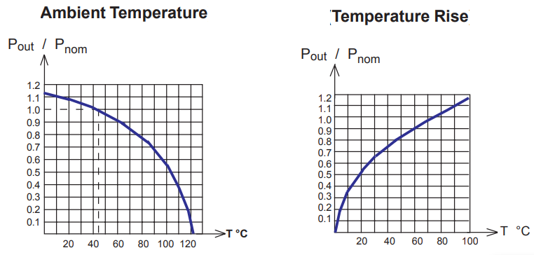
As can be seen from the graphs below, Talema standard toroidal transformers are designed for a temperature rise of 60 °C to 70 °C at nominal load. When choosing a transformer size, the ambient temperature and heat sink coefficient of the mounting place must be taken into consideration. Figures show the typical temperature change which occurs as a function of output power or overload.
Step 9: Multiple Windings or Single Winding (Autotransformer)
An autotransformer allows smaller dimensions and a more economical overall design in cases where galvanically separated windings are not required. The same transformation of voltage and current can be obtained with a single winding autotransformer as with a normal two winding transformer. There are two major differences:
- In the autotransformer, the secondary winding is common to both the primary and secondary winding.
- There is a direct copper connection between the primary and secondary circuits.

Autotransformers have lower leakage reactance, lower losses, smaller excitation currents, and they can be smaller and less expensive than dual winding transformers when the voltage ratio is less than 2:1. And, of course, they provide no isolation.
Talema has family approval for autotransformers to 25 KVA for UL5085 (general purpose transformers) and 40 KVA for UL60601-1 (transformers for medical and dental equipment) standards.
Step 10: Rectification
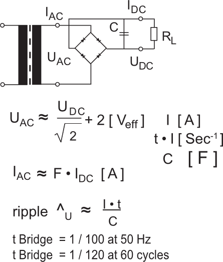
The below figures give formulae for the calculation of approximate values of the transformers and are primarily dependent on the size of the loading capacitor to be used. The applied form factor “F” is rated between 1.1 for smaller capacitors and 2.5 for relatively large capacitors.
Full Wave Bridge
Center-Tapped Bridge
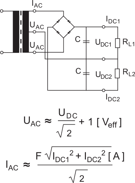
Step 11: Inrush Current
The characteristics which give the toroidal transformer advantages also contribute to a disadvantage: high inrush current with initial application of power. Talema is successful at designing transformers with low inrush current.
The absence of a gap in the toroidal core means that the maximum possible remanence (residual magnetization of the core in a particular direction and magnitude can be substantially more pronounced in a toroid when compared to an E-I laminate). This residual magnetism is the mechanism by which old computer core memories functioned. The core “stores” the static magnetic bias when the power is switched off. If the removal of power occurs at an unfavorable time, the strongest magnetic remanence will be stored in the core. When power is again applied to the primary, the peak inrush current may be as great as

where Vp-pk is the peak primary voltage, and Rp is the DC resistance of the primary winding, depending on the power capability of the transformer, and on how strongly the core was magnetized. This inrush current peak occurs for a short time during the first or second half period of the power sine wave.
There are several approaches for addressing inrush current:
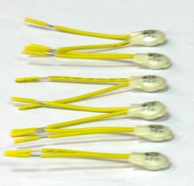
- Adding an NTC thermistor in series with the primary winding of the transformer
- Using slow-blow fuses for utilizing delayed actions
- Reduce the residual flux which will increase the magnetization current in the core. Methods used to reduce residual flux include introducing a gap or utilizing alternate materials or annealing methods.
Step 12: Thermal Protection
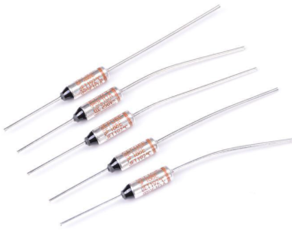
We will cover two types of thermal protection for toroidal transformers: one-shot fuse and auto-resettable thermal switch.
The purpose of these devices is to cut off the transformer in the event of overheating. The one-shot fuse is used primarily for protection from internal transformer faults, tripping at a preset temperature. The auto-resettable thermal switch provides intermittent protection from internal transformer faults and external overloads. This device opens at a preset high temperature and closes at a preset lower temperature. These devices are mounted internally to the transformer and wired in series with the primary or secondary winding.
One-Shot Fuse / Cut-off Fuse
Thermal Switch
