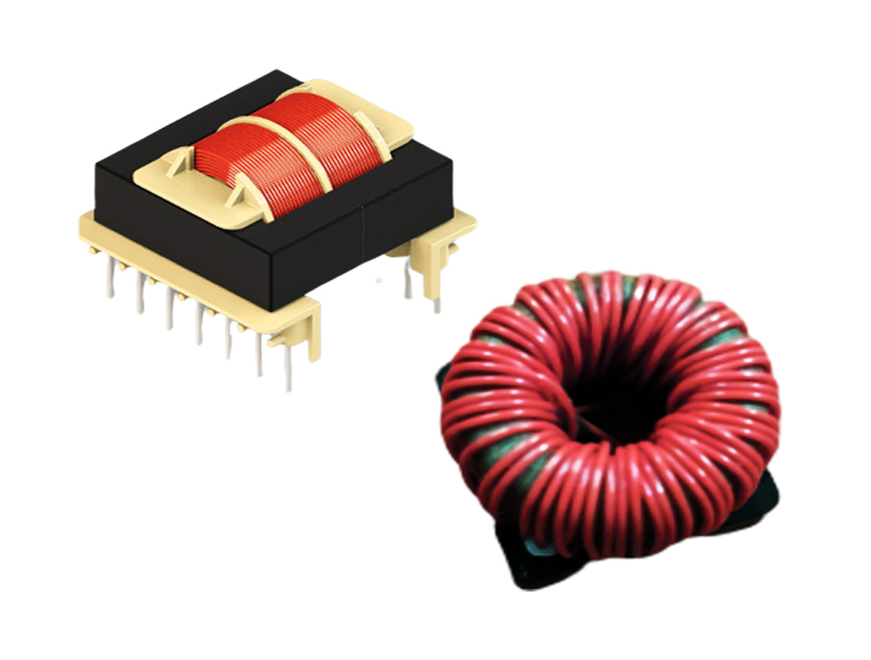
A gate driver is a power amplifier that accepts a low-power input from a controller IC and produces the appropriate high current gate drive for a power device. As requirements for power electronics continue to increase, the design and performance of the gate driver circuitry are becoming ever more important.
Power semiconductor devices are the heart of modern power electronics systems. These systems utilize many gated semiconductor devices such as ordinary transistors, FETs, BJTs, MOSFETs, IGBTs, and others as switching elements in switched-mode power supplies (SMPS), universal power supplies (UPS), and motor drives. Modern technology evolution in power electronics has generally followed the evolution of power semiconductor devices.
Power level requirements and switching frequency are increasing in the power electronics industry. The metal oxide semiconductor field effect transistor (MOSFET) and insulated gate bipolar transistor (IGBT) are two of the most popular and efficient semiconductor devices for medium to high power switching power supplies in most applications.
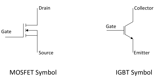
The gate of a MOSFET or IGBT is the electrically isolated control terminal for each device. The other terminals of these devices are source and drain or emitter and collector. To operate a MOSFET/IGBT, typically a voltage has to be applied to the gate that is relative to the source/emitter of the device. In order to drive these switching devices into conduction, the gate terminal must be made positive with respect to its source/emitter.
The power device switching behavior is affected by the parasitic capacitances between the three terminals, i.e., gate-to-source (Cgs), gate-to-drain (Cgd) and drain-to-source (Cds) which are usually non-linear and a function of bias voltage. Charging the gate capacitor turns the power device ON and allows current flow between its drain and source terminals, while discharging it turns the device OFF and a large voltage is blocked across the drain and source terminals.
The gate voltage of a power device does not increase unless its gate input capacitance is charged, and the power device does not turn on until its gate voltage reaches the gate threshold voltage (Vth). The Vth of a power device is defined as the minimum gate bias required for creating a conduction path between its source and drain regions. For operating a power device as a switch, a voltage sufficiently larger than Vth should be applied between the gate and source/emitter terminal.
Gate Drivers for Power Electronics
In high power applications, the gate of a power switch can never be driven by the output of a logic IC (PWM controller). Because of the low current capabilities of these logic outputs, charging the gate capacitance would require an excessive amount of time, most likely longer than the duration of a switching period. Hence dedicated drivers must be used to apply a voltage and provide drive current to the gate of the power device. This can be a driver circuit and it may be implemented as dedicated ICs, discrete transistors or transformers. It can also be integrated within a PWM controller IC.
A gate driver is a power amplifier that accepts a low power input from a controller IC and produces the appropriate high current gate drive for a power device. It is used when a PWM controller cannot provide the output current required to drive the gate capacitance of the associated power device.

The gate driver circuit is an integral part of power electronics systems. Gate drivers form an important interface between the high-power electronics and the control circuit and are used to drive power semiconductor devices. The output of DC-DC converters or SMPS mainly depends on the behavior of gate driver circuits, which means if the gate driver circuit doesn’t drive the gate of a power device properly, the DC-DC converter output will not be according to the design requirement. Therefore, the design of the gate driver circuit is critically important in the designing of power electronic converters.
Types of Gate Drivers
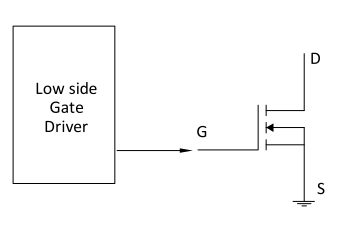
Low-Side Drivers — Used to drive ground referenced switches (low side switches).
High-Side-Low-Side Drivers — Used to drive two switches connected in the bridge arrangement (both floating & ground referenced switches).
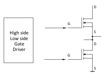
Gate Driver Isolation
Gate drive circuits for power inverters and converters often require electrical isolation for both functional and safety purposes. Isolation is mandated by regulatory and safety certification agencies to prevent shock hazards. It also protects low voltage electronics from any damage due to faults on the high power side circuit and from human error on the control side. The electrical separation between various functional circuits in a system prevents a direct conduction path between them and allows individual circuits to possess different ground potentials. Signal and power can still pass between isolated circuits using inductive, capacitive or optical methods.
Many applications of power devices (e.g., converters where high power density and high efficiency are required) require an isolated gate drive circuit. For example, in power converter topologies such as half-bridge, full-bridge, buck, two-switch forward, and active clamp forward, there are high y low switches because low side drivers cannot be used directly for driving the upper power device. The upper power devices require an isolated gate driver because the source and emitter of the upper devices are not sitting at the ground potential (floating).
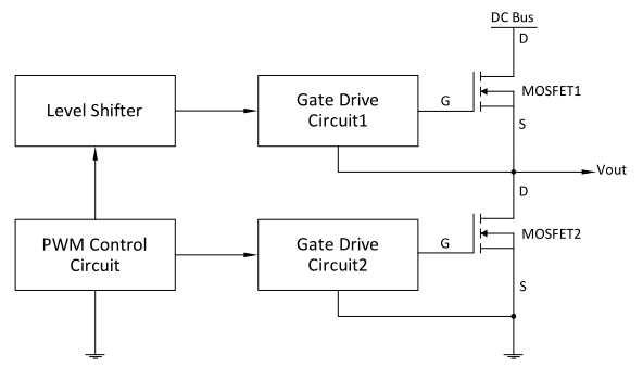
In a simple bridge topology structure with a driving circuit as shown here, the source terminal of switch 1 can be floating anywhere from ground to DC bus potential. Therefore two things are needed for driving high side switches:
- Floating supply — to provide power to any circuitry associated with this floating midpoint potential.
- Level shifter — to convey the PWM control signal to the floating driver circuitry.
Isolation Techniques
Basically, there are two popular techniques available to implement isolated gate drivers: magnetic (using gate drive transformers) and optical (using an optocoupler). Our next few articles will focus on the magnetic isolation technique, specifically the characteristics and design requirements for gate drive transformers.

