Following these 12 steps when designing gate drive transformers will ensure a long component life and optimal performanceSeguir leyendo
Talema – Nuvotem – NT Magnetics
Following these 12 steps when designing gate drive transformers will ensure a long component life and optimal performanceSeguir leyendo
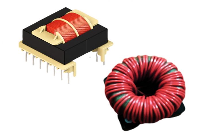
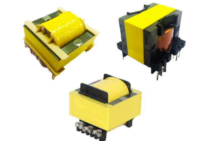
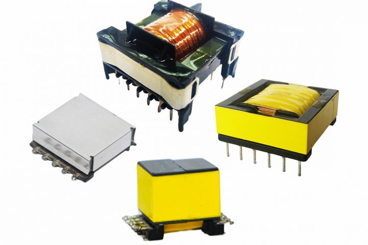
Several important factors need to be considered when designing an optimized gate drive transformer (GDT). This article discusses several GDT design considerations, as well as ideal applications for their use. Two of the critical components to control when designing a gate-drive transformer are the leakage inductance and distributed capacitance. High leakage inductance and distributed capacitance...Seguir leyendo
A gate drive transformer must reproduce the shape of an input pulse as accurately as possible at its secondary terminals. The performance of a gate drive transformer’s pulse characteristics is specified in terms of its effect on the shape of the pulse input current/voltage. It is important that the transformer must reproduce the shape of...Seguir leyendo
A gate drive transformer is optimized for transmitting rectangular electrical pulses with fast rise and fall times to activate or deactivate a switching device. Despite various floating channel MOSFET/IGBT driver ICs being available, a transformer-coupled gate drive is still the better option to use for high power applications for many reasons. For example, due to the multiple...Seguir leyendo
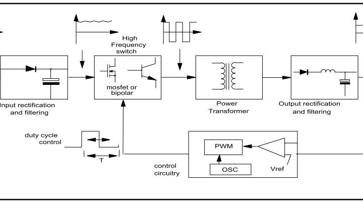
A gate driver is a power amplifier that accepts a low-power input from a controller IC and produces the appropriate high current gate drive for a power device. As requirements for power electronics continue to increase, the design and performance of the gate driver circuitry are becoming ever more important.Seguir leyendo
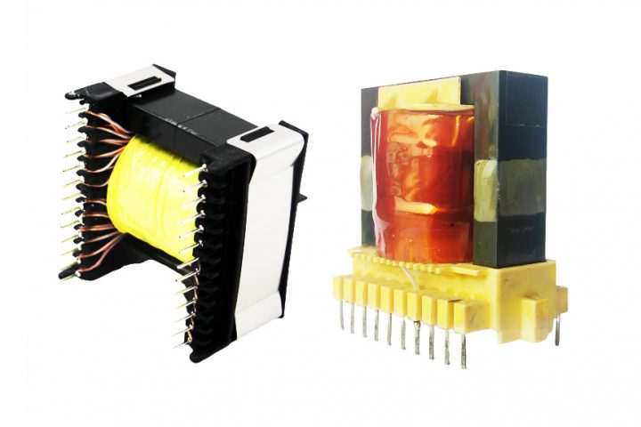
Designing magnetic components for SMPS can be challenging due to the increasing demands of modern electronics designs. Following these 12 steps can help engineers navigate the challenges and ensure a successful projectSeguir leyendo
Phase-shifted full-bridge (PSFB) converters reduce switching loss and increase efficiency by phase-shifting the gate signals between the leading leg and the lagging leg switches without additional circuitsSeguir leyendo
Demand for smaller electronics (and thus smaller power supplies) continues to increase. Resonant techniques are used to allow for high-frequency operation in switched-mode power supplies, which in turn allows for smaller componentsSeguir leyendo
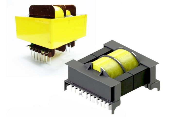
The fourth article in our series on switched-mode power supplies (SMPS) covers the main types of symmetrical isolated converter topologies: push-pull, half-bridge, y full-bridgeSeguir leyendo
Isolated SMPS topologies are split into two main categories depending upon how the transformer is utilized: asymmetrical and symmetrical. In this article, we discuss asymmetrical isolated converter topologies.Seguir leyendo