The increasing requirements of lighter, smaller and more efficient electronic products require power supply designers to develop AC-DC and DC-DC converters with high power density and efficiency. High switching frequency and high efficiency are the two methods used to improve power density and the profile of switched-mode power supplies (SMPS).
The effort to obtain ever-increasing power density in an SMPS has been limited by the size of passive components. Operation at higher frequencies considerably reduces the size of passive components such as transformers and filters; however, switching losses have been an obstacle to high-frequency operation.
Resonant techniques are used to reduce the switching losses in semiconductor devices and to allow for high-frequency operation. These techniques process power in a sinusoidal manner and the switching devices are softly commutated. Therefore, the switching losses and noise can be dramatically reduced because of its soft switching characteristics. Resonant techniques are used in both half-bridge and full-bridge converters.
The three most popular resonant converters are,
- Series resonant converter
- Parallel resonant converter
- LLC resonant converter
Series resonant converter
In a series resonant converter (SRC), the resonant inductor (Lr) and resonant capacitor (Cr) are in series and placed in series with the load. The resonant tank and the load act as a voltage divider.
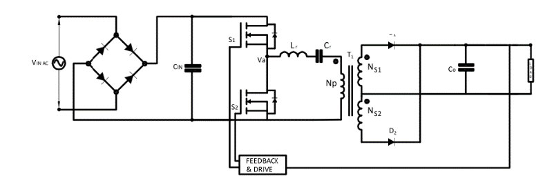
The impedance of the resonant tank can be changed by varying the frequency of driving voltage (Va).
The input voltage will be split between this impedance and the reflected load. Since it is a voltage divider, the DC gain of an SRC is always lower than 1 (maximum gain happens at the resonant frequency).
At light load condition, the impedance of the load will be very large compared to the impedance of the resonant network and all the input voltage will be imposed on the load. This makes it difficult to regulate the output at light load. Theoretically, frequency should be infinite to regulate the output at no load.
Advantages
- Reduced switching loss and EMI through Zero Voltage Switching & Improved efficiency
- Reduced magnetic components size by high-frequency operation
Disadvantages
- High circulating energy and high switching loss will occur at high input voltage. They are not suitable in application such (front end DC/DC application).
- Pulsating rectifier current from the output capacitor so limitation for high output current application.
- Cannot regulate the output at no load condition.
Parallel Resonant Converter
In a parallel resonant converter (PRC), The resonant capacitor (Cr) is placed in parallel with the load, inevitability requiring large amounts of circulating current. This makes it difficult to use parallel resonant topologies in applications with high power density or large load variations.
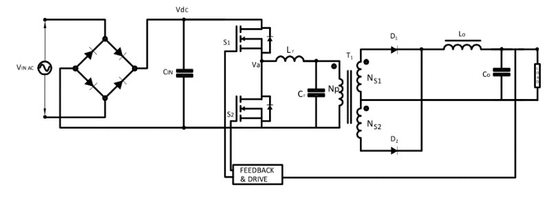
The impedance of the resonant tank can be changed by varying the frequency of driving voltage (Va). The transformer primary side is a capacitor, so an inductor is added on the secondary side to match the impedance.
Advantages
- No problem in output regulation at no load condition
- Continuous rectifier current from the output inductor, Hence it is suitable for high output current application
Disadvantages
- The primary side current is almost independent of load condition, significant current may circulate through the resonant network, even at the no-load condition
- High circulating energy and high switching loss will occur at high input voltage. They are not suitable in application such (front end DC/DC application)
Half-Bridge LLC Resonant Converter
The half-bridge LLC topology consists of a square-wave generator, a series resonant tank, a transformer, an output rectifier circuit, and an output filter.
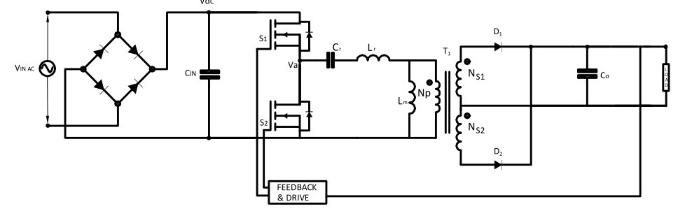
The series resonant tank is composed of a series resonant inductor Lr, a series resonant capacitor Cr, and the Lm formed by the magnetizing inductance of transformer T1. The series resonant inductor can be an external component or the leakage inductance of T1. The rectifier circuit which includes D1 and D2 converts the resonant current into a unidirectional current. The output filter Co modulates the high-frequency ripple current.
The LLC resonant converter uses transformer magnetizing inductance for generating one more resonant frequency, which is much lower than the main resonant frequency comprising resonant tank Lr and Cr. The LLC resonant converter is designed to operate at a switching frequency higher than the resonant frequency of the resonant tank Lr and Cr.
Switches S1 and S2 operate at 50% duty cycle and the output voltage is regulated by varying the switching frequency of the converter. The converter has two resonant frequencies: a lower resonant frequency Fr2 (given by Lm, Lr, and Cr) and a fixed higher series resonant frequency Fr1 (given by Lr and Cr only).
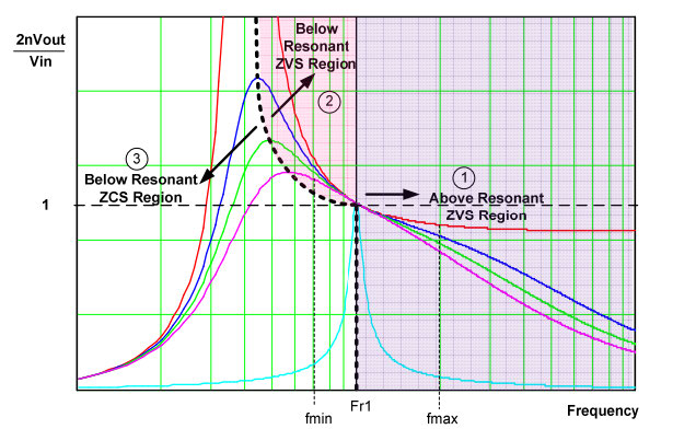
The typical frequency response of an LLC resonant converter is:
The two resonant frequencies are:


The quality factor of the resonant tank is:


RAC = Equivalent AC Resistance, n = Turns ratio
The characteristics of an LLC resonant converter can be divided into three regions based on the operation.
Region 1 is similar to SRC operation. When the switching frequency is higher than Fr1, the converter is running at the ZVS region and the magnetizing inductance does not participate in the resonance. This region, which is also called the inductive load region, the voltage gain of the LLC resonant converter is always less than one.
Region 2 is the multi-resonant converter (MRC) region. Between Fr1 and Fr2, the load condition will determine the operation of the converter under ZVS and ZCS conditions, converter voltage gain reaches its maximum value. In this region, the energy stored in the magnetic components causes ZVS for the opposite switching device.
Region 3 is the overloaded region. When switching frequency is higher than Fr2, the converter always runs at ZCS condition. This region is called the capacitive mode region, switches S1 and S2 are under hard switching and have high switching losses. So ZCS operation should always be avoided.
In general, the LLC resonant converter is designed to operate in Region 1 and 2 because of output regulation and ZVS operation. Switches S1 and S2 can be soft-switched for the entire load range by operating the converter under inductive load mode (ZVS region). It can be either above or below the resonant frequency Fr1. The required gain is determined by the relationship between the input and output voltage, which can be represented by:

g = Voltage gain for LLC resonant converter
Vo = Output voltage
VIN = Input voltage
From this equation, we can see that the lower the input voltage, the higher the voltage gain.
Advantages
- Narrow frequency variation over a wide line and load range, making this topology the best choice for front end DC-DC applications.
- ZVS capability for entire load range, low turn-off current, therefore the switching loss is very low.
- Zero voltage switching even at no load condition
- All essential parasitic elements, including junction capacitances of all semiconductor devices and the leakage inductance of the transformer, are utilized to achieve soft-switching.
- No output choke required, resulting in cost savings
- Integrated magnetics: When a transformer is used in an LLC converter, the magnetizing inductance and leakage inductance can be used in resonant circuit instead of using a separate external inductor
- High efficiency of > 96% and high power level up to 1 kW.
Disadvantages
- Higher ripple current on the secondary so lower ESR capacitors needed
Applications
- LED and LCD televisions
- Computers and laptops
- Industrial LED lighting
- High-end audio
- Home appliances
- Industrial battery chargers